

Pizza Delivery IoT Project Pt. 2


Continuing from Pizza Delivery IoT Project Pt. 1, I have completed much of the circuit design on my breadboard and completed the basic code necessary to interact with the sensors on the board.
To interact with the various components on the board, I have added the following packages to my project file:
<ItemGroup>
    <PackageReference Include="Iot.Device.Bindings" Version="2.2.0" />
    <PackageReference Include="System.Device.Gpio" Version="2.2.0" />
</ItemGroup>
System.Device.Gpio allows your .NET code to interact with the GPIO pins attached to the RaspberryPi. This is the primary way that you can extend the RaspberryPi with things like sensors, LED's and switches.
The Iot.Device.Bindings library works with the Gpio library and contains the code necessary to interact with a selection of common sensors and devices. In this case, I am using the library for support of the DHT11 temperature and humidity sensor.
Interacting with the sensor
As I mentioned, interacting with the DHT11 sensor can be done by adding the IoT.Device.Bindings project to your project, and then instantiating the class:
private Iot.Device.DHTxx.Dht11 _sensor;

using GpioController _controller = new GpioController (PinNumberingScheme.Logical);
var _sensor = new Iot.Device.DHTxx.Dht11 (_pinNumber, PinNumberingScheme.Logical, _controller, false);
The DHT11 sensor has three pins attached to it. The first, leftmost, pin requires a constant +5-volt connection supplied by the RaspberryPi. The last, rightmost pin is connected to one of the ground pins on the RaspberryPi. Finally, the middle pin on the sensor is connected to one of the generic GPIO pins, in my case I have it connected to pin 16. This pin is used to read data from the sensor. Warning: If you accidentally reverse the wiring on the DHT11, connecting positive 5v to the rightmost connector and ground to the leftmost sensor, the device will be destroyed very quickly. I did this accidentally when prototyping and my first sensor was connected backward. The sensor quickly overheated and melted.
The library for interacting with the sensor allows for two methods for retrieving data.
_sensor.TryReadTemperature (out temp);
This method will attempt to read the current ambient temperature from the sensor. The other method:
_sensor.TryReadHumidity (out humidity);
Attempts to read the current relative humidity from the sensor.
Each of these methods returns a true or false indicating rather the reading was successful or not. In practice, I found that the sensor returned a large number of failures when attempting to read from the device. To cope with this, I created a wrapper class and implemented some retry logic for each of the readings.
using System;
using System.Device.Gpio;
using UnitsNet;

namespace RpiDotNet
{
    public class EnvironmentSensor
    {
        private Iot.Device.DHTxx.Dht11 _sensor;
        private GpioController _controller;
        private int _pinNumber;
        public EnvironmentSensor (GpioController controller, int pinNumber)
        {
            _controller = controller;
            _pinNumber = pinNumber;

            _sensor = new Iot.Device.DHTxx.Dht11 (_pinNumber, PinNumberingScheme.Logical, _controller, false);
        }

        public Conditions GetConditions ()
        {
            Conditions conditions = new Conditions ();
            Temperature temp = new Temperature ();
            RelativeHumidity humidity = new RelativeHumidity ();

            bool successfull = false;
            for (int i = 0; i < 20; i++)
            {
                successfull = _sensor.TryReadTemperature (out temp);
                if (successfull)
                {
                    conditions.Temperature = temp.DegreesCelsius;
                    break;
                }
                else
                {
                    Thread.Sleep (250);
                }
            }
            if (!successfull)
            {
                return null;
            }

            successfull = false;
            for (int i = 0; i < 20; i++)
            {
                successfull = _sensor.TryReadHumidity (out humidity);
                if (successfull)
                {
                    conditions.Humidity = humidity.Percent;
                    break;
                }
                else
                {
                    Thread.Sleep (250);
                }
            }

            return conditions;
        }
    }
}
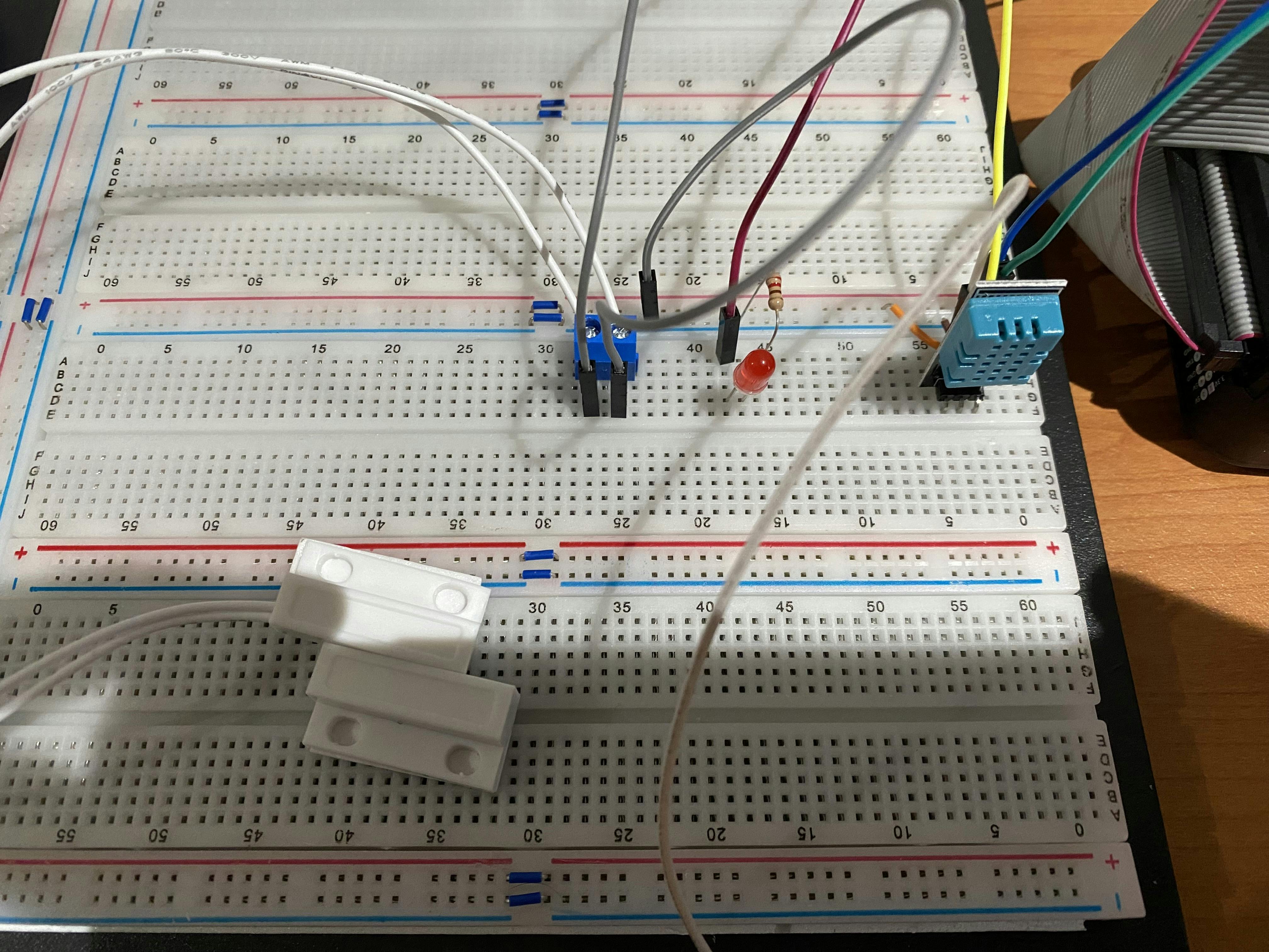
This temperature and humidity sensor is the main part of the IoT side of my project. However, I also wanted to add a few more items, as you can see in the image, I posted at the start of the blog post.
The LED is going to be a warning light for when the Pizza Delivery container goes outside of the acceptable bounds for temperature or humidity. For this light to work, I need to trigger a routine on the device to activate the warning light and make it flash. The basic functionality of the GPIO allows me to turn the light on or off, however, I need to extend that functionality with the ability to flash the light at a scheduled interval. Once again, I have written a wrapper class. Warning: If you are connecting an LED to a GPIO connector, you should always place a 1k ohm resistor in series with the LED. Failure to do so can burn out the LED.
using System.Device.Gpio;

namespace RpiDotNet
{
    public class WarningLight
    {
        private GpioController _controller;
        private bool _lightOn = false;
        private int _pinNumber;

        private bool _enableWarning = false;

        private System.Threading.Timer _warningTimer;

        public WarningLight (GpioController controller, int pinNumber)
        {
            _controller = controller;
            _controller.OpenPin (pinNumber, PinMode.Output);
            _pinNumber = pinNumber;

            // Create a timer object to handle the warnings for tempereatire being out of range.
            _warningTimer = new Timer (new TimerCallback (DoWarningLight));
        }

        public void BlinkLight ()
        {
            _lightOn = !_lightOn;
            _controller.Write (_pinNumber, ((_lightOn) ? PinValue.High : PinValue.Low));
        }

        private void DoWarningLight (Object? stateInfo)
        {
            BlinkLight ();
        }

        public void SetWarning (bool enable)
        {
            _enableWarning = enable;
            if (_enableWarning)
            {
                // Turn on the warning light and flash it every second.
                _warningTimer.Change (0, 1000);
            }
            else
            {
                // Disable the timer.
                _warningTimer.Change (System.Threading.Timeout.Infinite, System.Threading.Timeout.Infinite);
            }

        }
    }
}
I pass in the GPIO controller from my main class. I then use the GPIO controller to turn the light on or off. Setting the pin value to high turns the light on while setting the pin value to low turns the light off. I use a simple timer object to flash the light on a regular cadence once triggered. For the extended project, receiving a message from IoT Core indicating an out-of-range condition will trigger a call to the SetWarning method, which sets the timer off.
Finally, I have a magnetic switch attached to the board. I will use this to indicate when there is a pizza in the container that needs monitoring. When the magnetic switch reads as closed, the project will read the environmental conditions and send the results to AWS IoT core. When the switch is open, the collecting data will stop.
For reading the switch state, I can do this by interacting directly with the GPIO connectors. One side of the switch is connected to a GPIO pin, in this case, pin 17, and the other side of the switch is connected to a ground pin.
const int _SensorPin = 17;
_controller.OpenPin (_SensorPin, PinMode.InputPullUp);
_controller.RegisterCallbackForPinValueChangedEvent(
    _SensorPin,
    PinEventTypes.Falling | PinEventTypes.Rising,
    OnPinEvent);
Register CallbackForPinValueChangedEvent sets up and an event handler for the state of the switch changes. You then implement your event handler.
void OnPinEvent(object sender, PinValueChangedEventArgs args)
{
    if (args.ChangeType == PinEventTypes.Falling)
    {
        // Door is open. There is no need to send sensor data.
        Console.WriteLine ("Trigger");
        light.SetWarning (true);
    }
    else
    {
        // Door is closed, we should send sensor data.
        Console.WriteLine ("Clear");
        light.SetWarning(false);
    }
}
A switch state of "Falling" indicates that the switch is in an open state, indicating that the door is open. Alternatively, a state of "Rising" will indicate that the switch is in a closed state, and the door has been closed.
One final thought on the magnetic switch setup. Initially, I tried to connect the magnetic switch to GPIO pin 21. However, I found that when my switch was connected I got a stream of rising and falling state changes being registered on the pin when the switch was closed. By moving my magnetic switch to pin number 17 the issue with the stream of rising and falling messages stopped. What I noticed is that PIN 17 is on the opposite side of the GPIO break out as the DHT11 sensor.
Well, that's it for this blog. Next time I will start wiring up the IoT Core connectivity to the unit.